|
|
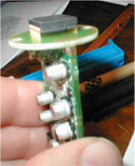
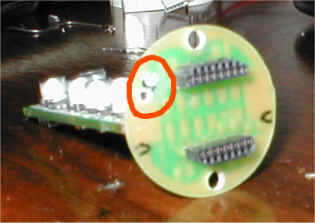
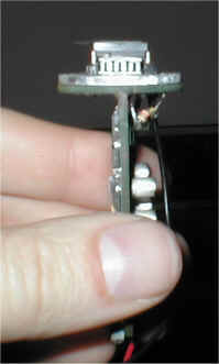
Its worth marking which way round the CCD goes
as it won't work if put back in upside down!! As the Pelt
and heatsink are about 5mm think we need someway to raise the
CCD from the board. |
 |
|
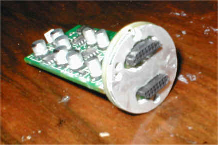
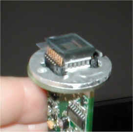
These DIL headers from Framos in the UK have the
right pin spacing for the CCD and give a suitable increase in
clearance from the PCB. |
  |
|
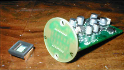
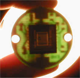
As the power leads to the pelt need to come out
of the back of the camera some holes need to be drilled in the
front PCB. Its worth checking where the tracks run. |
 |
|
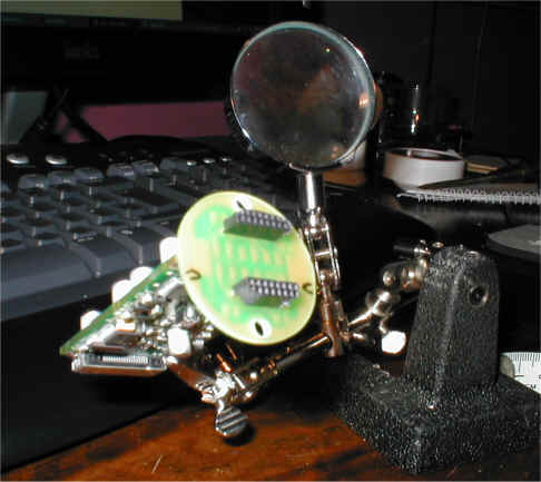
Next we have the heatsink. This passes
heat from the hot side of the pelt to the metal parts of the
camera. As PCBs conduct heat quite well this part might
not be essential. |
|
|
|
Now the pelt goes in with some thermal compound.
This pelt is from RS components 189-1576. Its can be run
at up to 2V 2A and is about 9mm square. |
  |
|
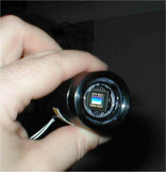
Now the CCD can go back. It gets a
bit messy with the paste so covering the ccd with a bit of
plastic keeps it clean. |
 |
|
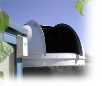
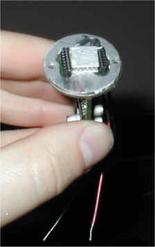
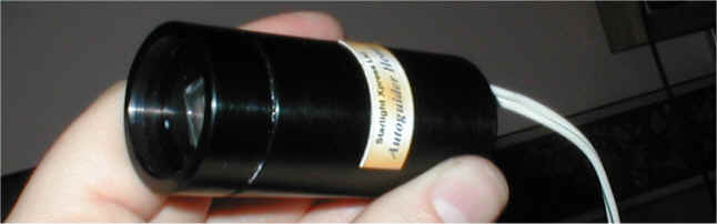
Put the case back together after fitting an
optical window to the front. A circular microscope slide
cover slip worked well for me. Next make a power supply
for the pelt.
|
|
|
|