Trust Spacecam 200 Modification.
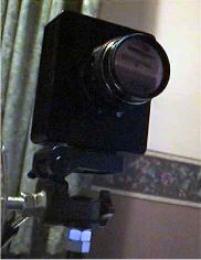 |
The Trust spacecam 200 is
based on the ov7620 cmos sensor which is also
used in many other webcams. This chip is
described as a camera on a chip as it contains
all the circuitry needed to take pictures, set
exposures, convert to digital, write to sram,
etc. The only other chips needed is the SRAM and
a USB bridge. The on chip timing circuitry allows
exposures up to 1/30 th of a second however the
facility for another device to control the length
of exposure is given by the FREX pin.
|
Data sheet is here
What this mod does is control the signal to FREX. As long
as FREX is logical high the chip will be exposed. This
time is determined by a 555 timer and can be altered
between 0.5-10 seconds with a potentiometer. In order to
work the exposure process needs to be synced to the
vertical sync signal hence the second lead to be soldered
to the chip. The main tools required to make the mod is a
fine tipped soldering iron and some solder wick if things
do wrong!
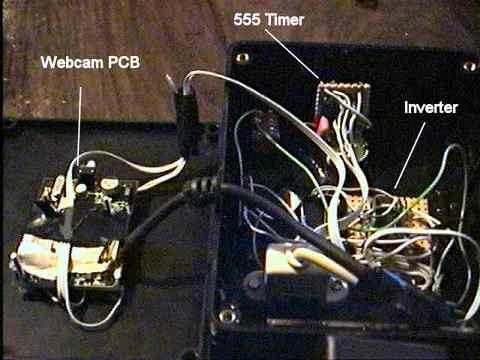
1 Make the controller circuit below.
2 Remove PCB from camera and remove lens
to expose chip
3 leads need to be soldered on to pins 4 and 16. The pin
numbering is below.
(Tip: cut a small piece of insulation tape
and stick it on the pcb next to the pin to be soldered
to. Take a 4" bit of insulated cable and remove 1
strand of wire. Fold in 2 and twist to make a very small
loop. Apply solder to the loop and solder to the pin
without adding fresh solder. The solder used to connect
the cmos to the board has quite a high mp so don't be
afraid to used plenty of heat)
4 connect up to the controller board taking 5v and 0v
from USB connections (red and black leads)
5 mount in project box.
 |
In order for the FREX signal to control
the exposure the camera must be in progressive scan mode.
The standard driver uses interlaced for all modes except
600x480x16. In order to get round this the driver needs
to be modified as follows:-
1 download new
7620p.set here.
2 Disconnect camera
3 backup the copy in windows/ovtcam/ and replace with the
new version.
4 remove the spacecam driver from control panel- imaging
devices.
5 Connect camera.
In addition to giving a 24bit progressive scan mode the
new driver also:-
Set all amps to max
Minimises the A/D converter range
Turns off image compression over USB
Turns off vertical and horizontal line emphasis.
Turns off contrast enhancement and noise removal.
Makes a nice cup of tea.
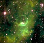
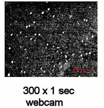
Limitations.
The cmos chip works by first filling the photo detectors
with charge. These detectors are made to be leaky with
the charge leaking away faster the more photons fall on
them. Apart form inherently not being very sensitive the
max exposure is limited by the speed at which the charge
leaks out of the chip in the dark. This shows up as
increasingly high backgrounds until the image becomes
white. With out cooling the chip exposures of around 4
seconds are possible. Given these limitations the mod
does produce a camera capable of catching some deep sky
objects on a £25 camera.
 |
 |
A further, although probably unworthwhile,
refinement is to add cooling. My first look at cooling
this camera comprised of filling the project box with dry
ice. What I saw was a dramatic decrease in the background
until condensation shorted out the camera! I now have a
slightly more elegant solution.
The cmos is a high density 40 pin device
and is unlikely to come off the board easily so the
normal cool finger peltier solution is not really on.
Instead I built a masking tape dam around the camera PCB
and filled the back of the board with epoxy potting
compound. This stuff has good thermal conductivity and
good electrical resistance. When it hardens it provides a
flat surface to mount a peltier. A cross section is
below. When adding a peltier to a camera remember that
apart from pumping a small amount to heat they also
produce a lot of heat so a big heatsink and fan is in
order. Although the background decreases sensitivity is
not dramatically increased.
For a description of a very nice spacecam 200 mod and
some better pictures see the QCUIAG site.
|