The mod was developed using a vesta 675
and the pictures are of the same. As the mod really
concerns just the connections to the 16510 then the mod
should work with any CCD camera using this chip. It is
worthwhile making 1 check first though. Using a
multimeter see if pins 8 and 13 on the 16510 are
electrically connected (0 ohms). If they are not the mod
should still work but the control circuit will need a
small change (email me smunch@clara.co.uk). If pins 8 and
13 are connected then you are in business.
Dismantle the camera and disconnect the CCD PDB. The
camera PCB is pretty hardy and seems to tolerate abuse
quite well. However do take antistatic precautions and
check your work with a magnifier and multimeter to see if
any solder bridges occur.
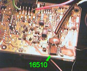 |
The vesta camera PCB has 2 sides. Top has
the 3 large IC's and the bottom holds the 16510 (near the
ccd pcb connector).
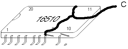
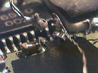
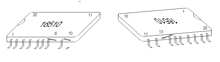
Firstly locate the 16510 and its pin numbering (pin 1
towards the CCD connector side). Now using some solder
wick remove the solder from under legs 8,10,and 13. Then
using some heat and a small blade (eg jewllers
screwdriver) lift these legs.
This is really the only bit were you could
damage the camera. Lift the legs carefully so as not to
snap them.
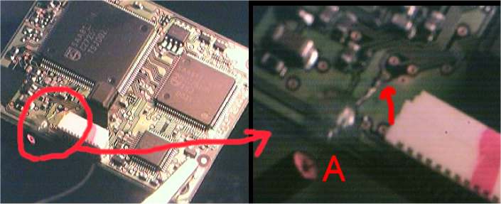
Next solder a wire to the pad below pin 13 or pin 8.
Alternatively use a multimeter to track back to a more
convenient connection eg the via (hole) where the signal
passes from one side of the PCB to the other (see
picture). This is lead A on the circuit diagram
Very fine wire is needed and I have been
using a single strand from an old piece to ribbon cable.
So as not to risk snapping it fix it somehow to the PCB
(insulation tape or expoy glue for example)
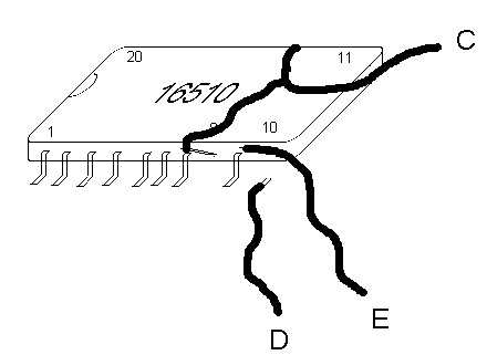
Now solder wire to the raised legs 13 and
8 of the 16510.
To achive this without risking adding a
large lump of solder, I made very small loops in the wire
and added a small amount of solder to these. The wire was
then placed against the chip leg and heat applied. It is
very important not to tug on these wires when soldered in
case the IC legs snap, so again fix the wire to the PCB.
If you don't need the shutter function then the tricky
bits are finished. However if you would like to keep the
shutter control available then wires also need soldering
to pin 10 and the pad below pin 10.
Care is needed for this lower lead as
there are a number of contact pads on the PCB close to
where this lead will run. Try first covering the PCB in
this area with insulation tape.
The last bit of work on the pcb is to
attach wires to the 5V and 0V of the USB connector to
power the logic ic's (see pic at top of page, 5V red wire
and 0V green).
Then all that's left is to connect up all
the wires (nb lead B is from pin 2 of printer port) and
double check for them solder bridges. To test the camera
connect to USB but not printer port. The camera should
work as normal except the shutter control will not work.
Then download the software on the next page, connect to
printer port and try a long exposure. During the exposure
the preview window should turn black.
If all this works then WELL DONE you now
have a deep sky capable colour webcam!!!!!
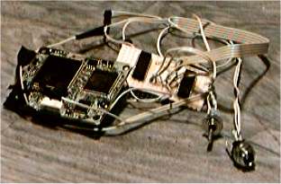 The finished mod
(nb
original 2 chip mod showen). The finished mod
(nb
original 2 chip mod showen). |
|